Guide

Single Spindle Slashers

Setting up and Optimising your machine

Video guide to setup and optimise your machine.

Step-by-step guide to setup and optimise your machine.

The slip clutch is designed to slip so that the gearbox and driveline are protected if the cutter strikes an obstruction. A new slip clutch or one that has been in storage over the winter may seize. Before operating the cutter, make sure it will slip by performing the following operation:

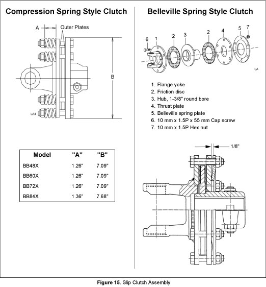
Compression Spring Style Clutch

  1. Turn off tractor engine and remove key.
  2. Loosen nuts on springs until the springs can rotate freely, yet remain secure on the bolts.
  3. Mark outer plates of slip-disc clutch as shown in Figure 15.
  4. Securely attach implement to the tractor and start the tractor.
  5. Engage PTO for several seconds then quickly disengage it.
  6. Turn tractor off and remove key.
  7. The friction lining plates should have “slipped”. Check the marks placed on the outer plates of the slip-disc clutch in step 3 to make sure this is the case.
  8. If clutch does not slip, check assembly for oil, grease and debris. Clean if necessary.
  9. Reassemble clutch and tighten bolts no more than 1/8 of a turn at a time until desired setting of 1.26″ on BB48X, BB60X and BB72X cutters is reached. For BB84X cutters, set to 1.36″. See Figure 15.
  10. If excessive slippage continues, check lining plates for excessive wear. They are 1/8″ thick when new and should be replaced after 1/32″ of wear to ensure proper operation.

Belleville Spring Style Clutch (Older BB84X Only)

  1. Turn off tractor engine and remove key.
  2. Remove driveline from tractor PTO.
  3. Loosen six 10 mm cap screws (6) to remove all tension from Belleville spring plate (5).
  4. Hold clutch hub (3) solid and turn shaft to make sure clutch slips.
  5. If clutch does not slip freely, disassemble and clean the thrust plate faces (4), flange yoke (1), and clutch hub (3).
  6. Reassemble clutch. Tighten Belleville spring (5) until it is against the thrust plate (4) of the clutch, and then back off each of the six nuts by two full revolutions. The gap between Belleville spring and thrust plate should be 1/8″ as shown in Figure 15.
  7. If a clutch continues to slip when the spring is compressed to 1/8″, check friction discs (2) for excessive wear. Discs are 1/8″ when new. Replace discs after 1/16″ wear. Minimum disc thickness is 1/16″.

  1. Do not let excess grease collect on or around parts, particularly when operating in sandy areas.
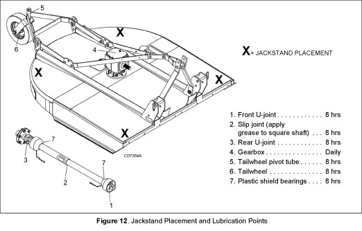
  2. See Figure 12 for lubrication points and frequency of lubrication based on normal operating conditions. Severe or unusual conditions may require more frequent lubrication.
  3. Use a lithium grease of #2 consistency with a MOLY (molybdenum disulfide) additive for all locations unless otherwise noted. Be sure to clean fittings thoroughly before attaching grease gun. One good pump of most guns is sufficient when the lubrication schedule is followed.

Gearbox Lubrication

  1. For gearbox, use a high quality gear oil with a viscosity index of 80W or 90W and an API service rating of GL-4 or -5 in gearboxes.
  2. Fill gearbox until oil runs out the side plug on gearbox. Check gearbox daily for evidence of leakage, and contact your dealer if leakage occurs.

Driveline Lubrication

  1. Lubricate the driveline slip joint every eight operating hours. Failure to maintain proper lubrication could result in damage to U-joints, gearbox, and driveline.
  2. Lower cutter to ground, disconnect driveline from tractor PTO shaft, and slide halves apart but do not disconnect from each other.
  3. Apply a bead of grease completely around male half where it meets female half. Slide drive halves over each other several times to distribute grease.

News
Tech Tips
Newsletter

Consider subscribing to our newsletter to receive the latest news, upcoming events and up-to-date tips on machine maintenance. 

Dealer Assembly & Service

The information in this section is written for dealer service personnel. The repair described here requires special skills and tools. If your shop is not properly equipped or your mechanics are not properly trained in this type of repair, do not attempt this repair.

Assembly of this slasher is the responsibility of the Woods dealer. If should be delivered to the owner completely assembled, lubricated, and adjusted for normal slashing conditions.

The slasher is shipped partially assembled and intended to be handled in the vertical position. Use appropriate lifting devices to move into horizontal position for assembly.

Assembly will be easier if aligned and loosely assembled before tightening hardware. Recommended torque values for hardware are located in the Bolt Torque Chart in this machines manual.

Complete Dealer Check Lists when you have completed the assembly.

Pre-Delivery Checklist

Inspect slasher thoroughly after assembly to make sure it is set up properly before delivering it to the customer. The following check list is a reminder of points to inspect. Check off each item as it is found satisfactory, corrections are made, or services are performed.

  • Check all bolts to be sure they are properly torqued.
  • Check that all cotter pins are properly installed and secured.
  • Check that PTO shaft is properly installed per operators manual.
  • Check that gearbox is properly serviced and seals are not leaking. Failure to fill the gearbox with oil will result in damage to the gearbox.
  • Check and grease all lubrication points as identified under Lubrication Information in this machines manual.
  • Check that blades have been properly installed and are spinning in the correct direction.
  • Check that all safety decals are installed and in good condition. Replace if damaged.
  • Check that the correct Operators Manual is included.
  • Check that shields and guards are properly installed and in good condition. Replace if damaged.

Delivery Checklist

  • Show customer how to make adjustments. Describe the options available for this slasher and explain their purpose.
  • Explain importance of lubrication to customer and point out lubrication points on slasher as per manual.
  • Present Operator’s Manual and request that customer and all operators read it before operating equipment. Point out the manual safety rules, explain their meanings and emphasize the increased safety hazards that exist when safety rules are not followed.
  • Point out all guards and shielding. Explain their importance and the safety hazards that exist when not kept in place and in good condition.
  • For mounted units, add wheel weights, ballast in front tires, and/or front tractor weight to enhance front end stability. A minimum 20% of tractor and equipment gross weight must be on front tractor wheels. When adding weight to attain 20% of tractor and equipment weight on front tractor wheels, you must not exceed the ROPS weight certification. Weigh the tractor and equipment. Do not estimate!
  • Ensure PTO shaft is installed at the correct length.
  • Show customer how to make sure driveline is properly installed and that spring-activated locking pin or collar slides freely and is seated in groove on tractor PTO shaft.
  • Show customer how to determine the turning limits of the CV PTO driveline.
PROBLEM POSSIBLE CAUSE SOLUTION
Does not cut
  • Dull Blades
  • Worn or broken blades
  • Incorrect PTO speed
  • Ground Speed too Fast
  • Drive not functioning (blades do not turn when PTO is running)
  • Gearbox malfunction
  • Excessive clutch slippage
  • Incorrect Blade Direction
  • Sharpen blades
  • Replace blades (replace pair)
  • Set at rated PTO speed
  • Reduce ground speed
  • Check drive shaft connection & clutch. Check gearbox
  • Repair gearbox
  • Adjust clutch or replace plates
  • Check to be sure blade edge is correct for direction of rotation
Streaks or rugged cut
  • Broken or worn blades
  • Attitude incorrect
  • Ground speed too fast
  • Excessive cutting height
  • Excessive lush and tall vegetation
  • Replace or sharpen blades
  • Level machine
  • Reduce ground speed
  • Lower cutting height (Note: set height so blades do not frequently hit the ground
  • Recut at 90° to first pass
Excessive side skid wear
  • Running with skids continuously on ground
  • Raise cutting height by adjusting wheel & tractor linkage
Excessive clutch slippage
  • Clutch out of adjustment
  • Clutch discs worn; wear stops contacting opposite plate
  • Blades hitting ground
  • Adjust clutch
  • Replace discs
  • Raise cutting height
Vibration
  • Broken blade
  • Bearing failure
  • Hitch length incorrect
  • Universal shaft not aligned
  • Flexible coupler is binding
  • Bent blades or disc
  • Replace blades in parts
  • Check gearbox shafts for side play
  • Reset hitch length
  • Adjust input shaft to be parallel to output shaft of tractor
  • Lubricate grease fitting on spline yoke
  • Replace blades/disc
Blades hitting deck
  • Bent blades or crossbar
  • Replace bent blades or crossbar
Blades hitting each other (Dual Spindle only)
  • Side drive failure
  • Retime blades, or replace rubber coupler disks. See operators manual.
Unit will not raise (Dual Spindle & Batwing only)
  • Low oil
  • Add hydraulic oil.
Unit doesn’t cut level (Batwing Only)
  • Wing section cuts lower than center
  • Wing section cuts higher than center
  • Lengthen turnbuckle connecting center yoke to wing wheel yoke
  • Shorten turnbuckle connecting center yoke to wing wheel yoke


Latest news and promotions

Subscribe To Our Newsletter

Get notified about new products, new articles and promotional specials.